
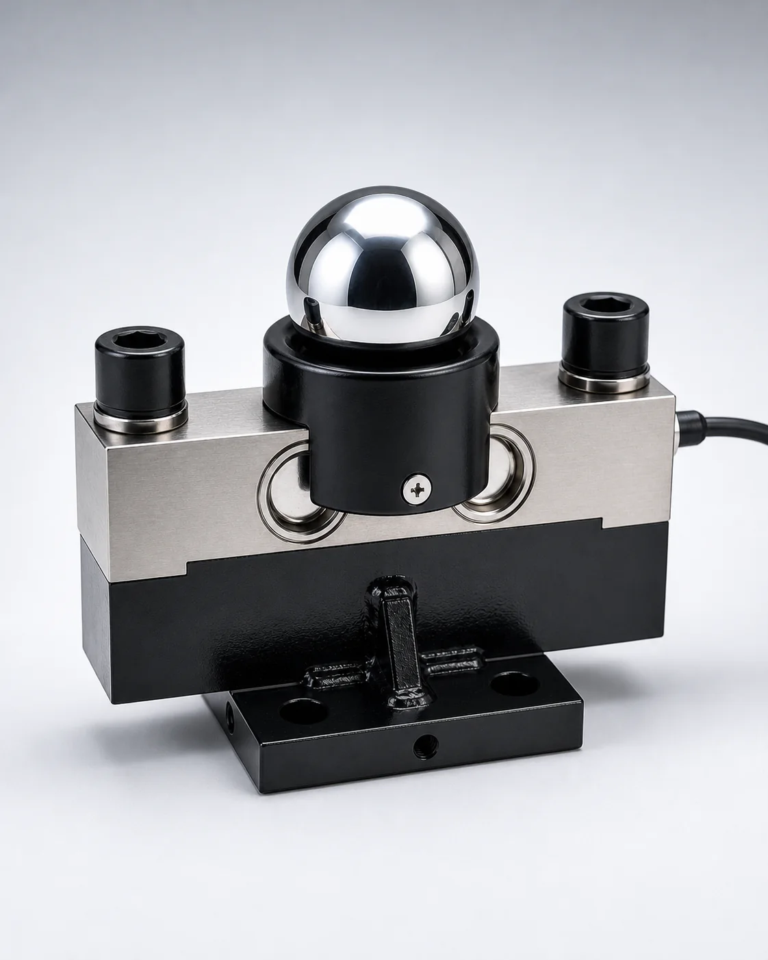
Primary sensingCore category
Load Cells
Match the sensor to load path, capacity, mounting geometry, dimensions, loading direction, cable and environment.
Explore ProductsChoose a language for this website.
Load Cells · Indicators · Weighing Components
ANTORIS helps machine builders specify load cells, weighing sensors, indicators and supporting components around the exact demands of their equipment.
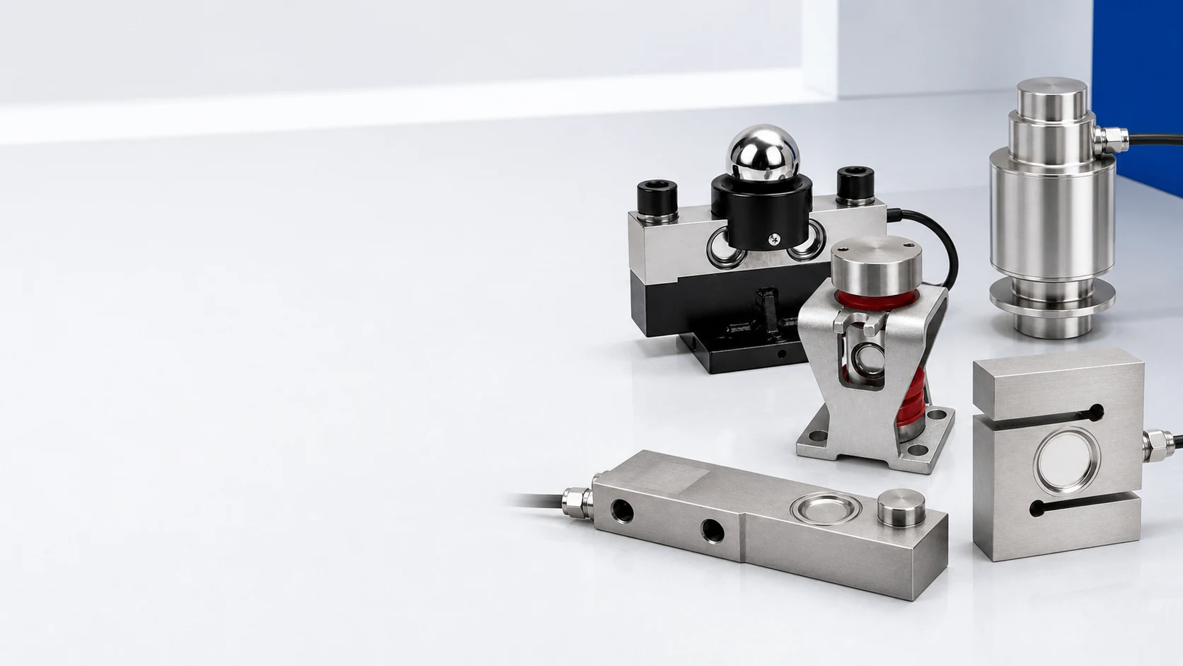
Start with sensing, then match transmission, summing, processing, control and display around the same application.
Match the sensor to load path, capacity, mounting geometry, dimensions, loading direction, cable and environment.
Explore Products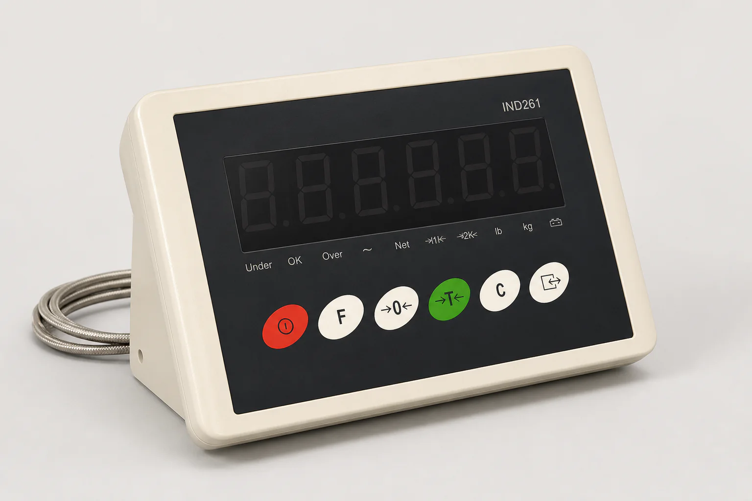
Align input, output, power, communication, display and control requirements.
Explore Products
Coordinate channel count, housing, cable entry, adjustment method and installation conditions.
Explore Products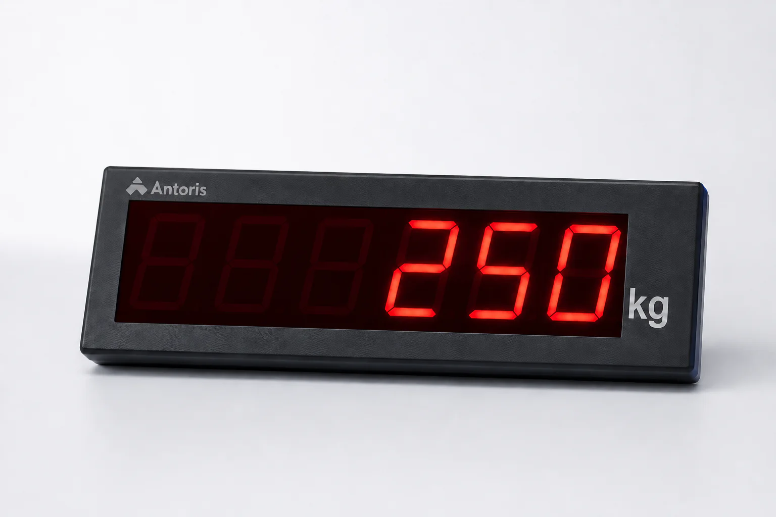
Extend weight visibility according to viewing distance, interface, enclosure and installation context.
Explore Products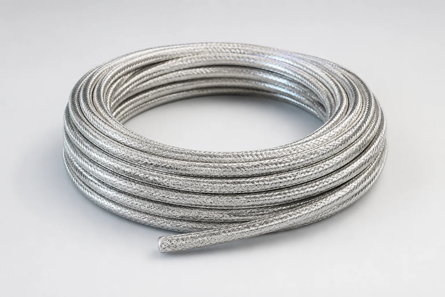
Match double-shielded cable to conductor, length, routing, connection and environmental needs.
Explore ProductsApplication to documented configuration
Product selection starts with the mechanical and signal conditions that shape fit, integration and document review.
Each confirmed input reduces uncertainty before a model is proposed.
Describe the equipment, weighing task, loading direction, mounting structure and the space available around the measuring point.
Review the working range, safety margin, outline dimensions, hole pattern, load point and the surfaces that transfer force.
Share temperature, moisture, washdown, corrosion, vibration, cable routing and other exposure relevant to the project.
Confirm the required output, power, communication and control path from sensor to junction box, indicator, PLC or remote display.
Compare the proposed configuration with available specifications, dimensional drawings, wiring information and approval references.
Different Buyers, Different Decisions
The application remains the starting point. The evidence and purchasing path change with the decision you need to make.
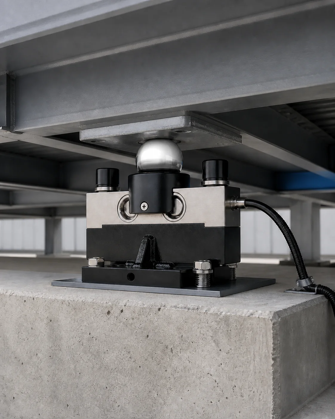
Focus on installation fit, consistent specifications, drawings, configuration control and repeatable purchasing.
Define the configuration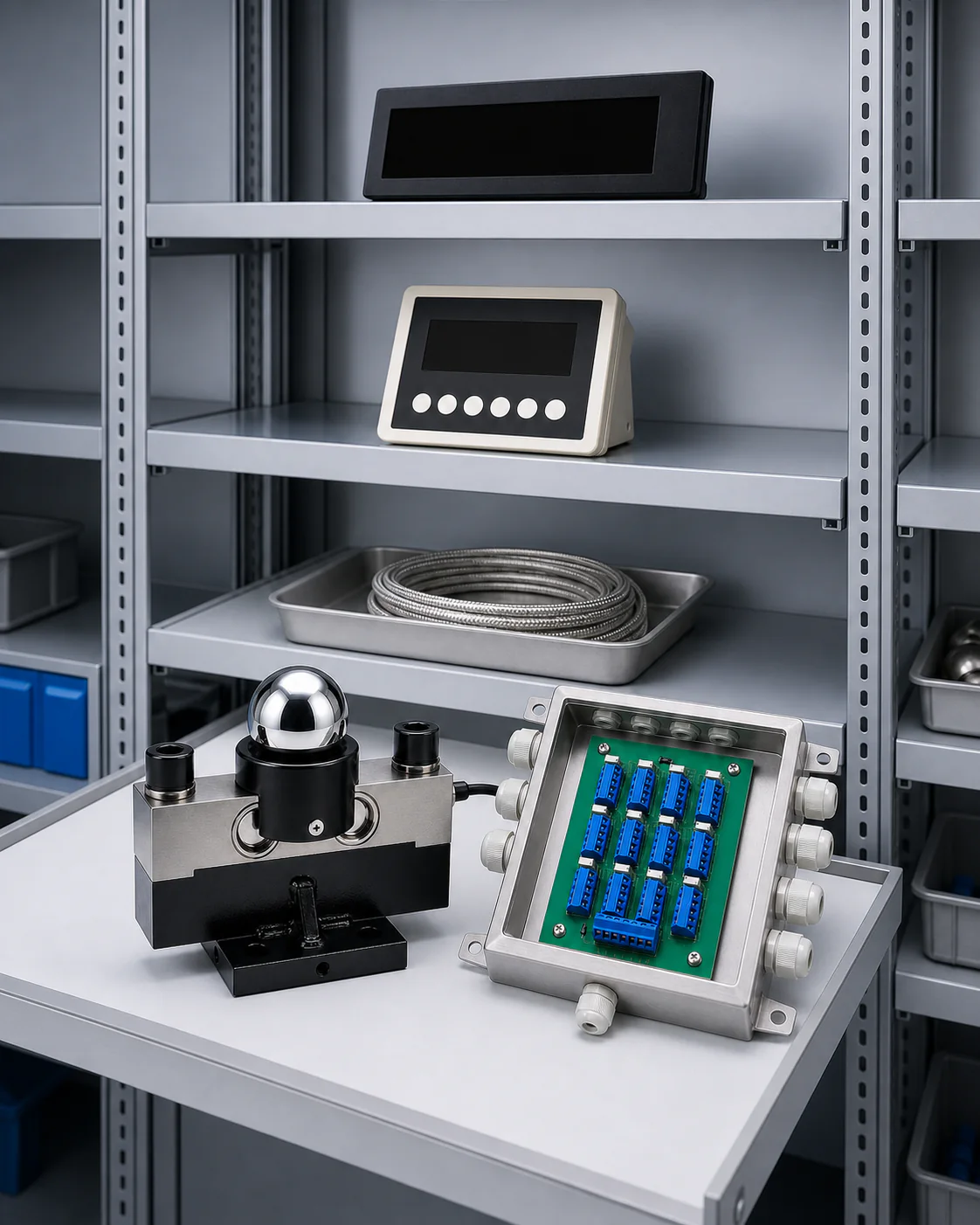
Focus on product-family coverage, model matching, replacement needs, mixed sourcing and clear sales documentation.
Map the product family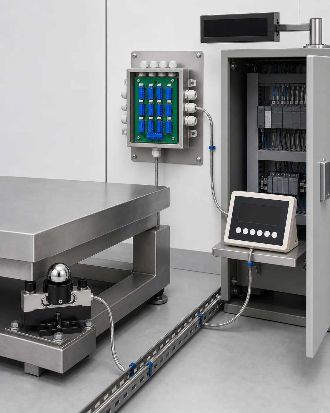
Focus on sensing, transmission, summing, communication, control, remote display and project compatibility.
Map the signal chainDocument availability varies by product and project. Request the current, model-specific files required for your technical review.
Review rated values, interfaces and listed operating parameters for the proposed model.
Request the current model fileConfirm outline dimensions, mounting details, cable exit and installation clearances.
Confirm the revision before useCheck conductor assignment, excitation, signal, communication and connection requirements.
Match the exact product versionAsk which model-specific test records or related documents are currently available for review.
Availability is model-specificState the certification or market requirement so the valid document status and model scope can be checked.
Confirm status by modelUse project identifiers, approved drawings and revision references to keep configuration decisions traceable.
Keep the approval path clear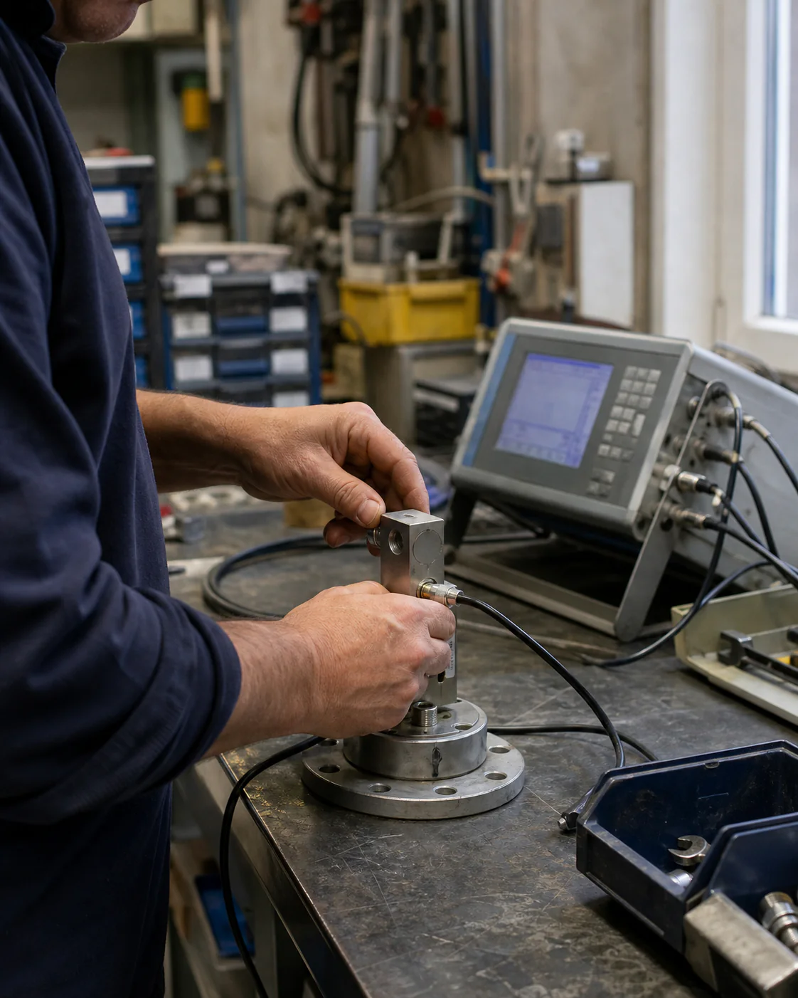
ANTORIS is based in Changzhou, Jiangsu, China. The product system is organized around load cells and the components that carry their signal through an industrial weighing application.
Equipment, load path, mounting space and operating conditions define the first review.
Model references, drawings, wiring information and revisions support clearer technical communication.
Certification, test and document scope should be confirmed against the exact product and current file.
Share what you are building. A model number, drawing or photo is enough to start.