
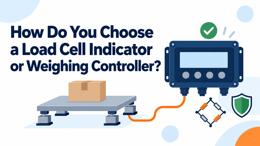
Most buyers start their load cell indicator search with the wrong question: "how many divisions does it display?" I get that message several times a month. Then the scale is built, the last digit drifts, and the indicator gets blamed. The real decision sits somewhere else — in what the scale must do, what it is wired to, and where it lives.
Choose a load cell indicator or weighing controller by matching three things before comparing specs: the scale's function (simple reading vs. batching, checkweighing, or control), the electrical setup it connects to (number of load cells, mV/V sensitivity, bridge resistance, excitation voltage), and the installation environment (indoor, outdoor, dust, humidity, unstable mains). Display resolution is the last consideration, not the first.
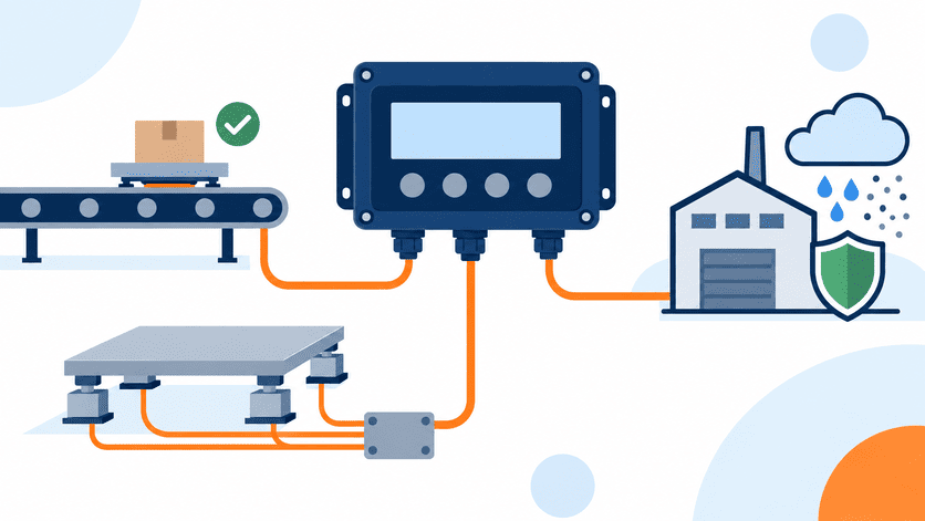
At ANTORIS I handle indicator model selection and technical confirmation for buyers, and I also see the after-sales tickets that come back. A large share of those tickets are not defects. They are selection mismatches. Below are the counter-questions I ask before recommending anything — and why each one matters more than the datasheet headline.
Why does display resolution mislead load cell indicator selection?
A buyer sends me a competitor spec sheet with 1/30,000 divisions highlighted in yellow. He assumes more divisions means a more accurate scale. Then the platform is assembled, the last digit never settles, and I receive a complaint about "indicator instability."
Display resolution does not create accuracy.[1] The load cell, the mechanical structure, and the installation determine what the scale can actually measure. A weighing indicator only amplifies, converts, filters, and displays that signal. Setting division count higher than the system can support simply makes normal mechanical noise visible on the screen.[2]

Where accuracy actually comes from
Think of the signal chain in order:
- Load cell — creep, hysteresis, non-linearity, temperature effect
- Mechanical structure — mounting, side loads, level, foot rigidity
- Cable and junction box — shielding, corner adjustment, connection quality
- Indicator — A/D conversion, filtering, calibration, display
The indicator sits at position four. It cannot recover information that was already lost at position one or two. This is a pattern we see repeatedly in selection and after-sales requests: the buyer upgrades the display, the problem stays.
How to set divisions sensibly
| Scale type | Common capacity | Realistic division approach |
|---|---|---|
| Bench / table scale | 3–30 kg | Higher divisions are usually workable — short, rigid structure |
| Platform scale | 100–3000 kg | Moderate divisions; mounting quality dominates |
| Floor / truck scale | 10–60 t | Conservative divisions; multiple cells, long cable runs |
| Hopper / tank weighing | Varies | Often lower divisions; piping, vibration, and wind matter |
My practical rule when advising OEM factories: choose divisions your assembled scale can hold steady in the customer's real environment, not the maximum the indicator brochure allows. A stable 1/3,000 reading builds more trust with an end user than a twitching 1/10,000 reading.
One more thing worth saying plainly. Legal metrology division classes are a separate topic from display divisions. A display can show many digits without the scale qualifying for any approval class. I will come back to that.
How do you check electrical matching between load cells and the weighing controller?
This is the quiet failure. The indicator arrives, gets wired to six load cells in parallel, and the readings jump or the unit "cannot drive" the setup. Nothing is defective. The numbers were never checked before the order.
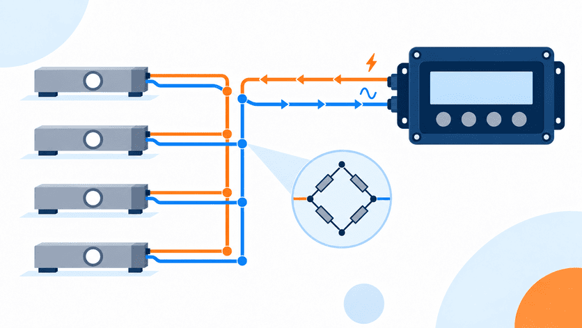
Electrical matching means confirming four values: excitation voltage supplied by the indicator, load cell output sensitivity in mV/V, load cell input/output impedance, and how many cells are wired in parallel. Together these determine whether the indicator can power the bridge network and resolve the resulting signal properly.
The five numbers I ask for before quoting
- Number of load cells in the system (1, 4, 6, 8…)
- Rated output of each cell (typically 2.0 mV/V or 3.0 mV/V)
- Input and output impedance of the cells (350 Ω and 700 Ω types are the common families)
- Cable length from cells to junction box, and junction box to indicator
- Whether a sense line (6-wire) connection is used or required
Why parallel connection changes everything
When you parallel load cells, the total bridge resistance drops. Four 350 Ω cells in parallel present roughly 87.5 Ω to the indicator's excitation supply. Eight cells present roughly 44 Ω.[3] The indicator has to source enough current for that load.[4] Every indicator has a stated limit on how many 350 Ω cells it can drive. Ignore it, and you get sagging excitation, drifting zero, or a display that simply will not calibrate.
Sensitivity matters too. Two cells with identical capacity but different mV/V ratings produce different signal levels at the same load. A 1 mV/V cell delivers half the signal of a 2 mV/V cell. If the indicator's input range is not suited to that, you lose usable resolution.
A short anecdote: a distributor once ordered indicators for stock, then sold them into a system with eight cells wired in parallel. The complaint came back as "unstable readings." We traced it to excitation loading, not the unit. Since then I always ask for cell count first, before anything else.
Quick pre-order checklist
| Item to confirm | Why it matters |
|---|---|
| Cells in parallel vs. indicator drive capability | Prevents excitation sag and calibration failure |
| mV/V sensitivity vs. indicator input range | Protects usable resolution |
| 4-wire vs. 6-wire connection | Long cables benefit from sense lines[5] |
| Junction box channel count (4 / 6 / 8) | Must match cell count and corner adjustment need |
| Cable shielding and single-point grounding | Reduces noise blamed on the indicator |
Collect these five values and send them to your supplier. It takes ten minutes and removes most field surprises.
Which outputs and communication interfaces should a load cell indicator have?
I have seen this sequence more than once. A batching machine is built, the indicator is installed, and only then does the engineer discover it has no RS485 port — or only two relay outputs where the batching logic needs four. The unit is fine. It is just the wrong unit.
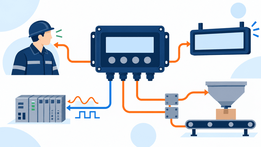
Decide outputs and communication at selection time, based on who consumes the weight data. A human operator needs a clear display. A PLC or automation system needs RS485 with Modbus RTU or a 4–20 mA analog output.[6] Batching and checkweighing need enough relay outputs for the control steps. Remote reading needs a large display driver output.
Start with one question: who reads the weight?
Case A — a person reads it. A platform scale in a warehouse. You need clear display, tare, zero, accumulation, maybe a printer port. Communication is optional.
Case B — a PLC or controller reads it. Packaging lines, filling machines, tank weighing. Now RS485 with Modbus RTU is usually the practical baseline, because most integrators already speak it. A 4–20 mA analog output is the fallback when the upper system only accepts analog signals.
Case C — a remote screen reads it. Truck scales, loading bays, workshop displays. You need an output that drives a remote LED display, plus a cable path that survives the distance.
Case D — the indicator itself controls something. Batching, checkweighing, filling. Here relay output count decides feasibility. Count your control steps before you count features:
- Coarse feed
- Fine feed
- Discharge / gate
- Over / under / accept sorting
- Alarm
A two-step filling process needs fewer outputs than a three-material batching sequence. Write the sequence down first.
Function features that change the model choice
- Accumulation — for logistics and shipping records
- Peak hold — for force testing and destructive checks
- Setpoint / comparison — for checkweighing accept-reject logic
- Multiple calibration modes — helpful for OEM production lines assembling many units
For distributors building a stock list, my honest advice is to standardize on one communication-capable model plus one basic reading model, rather than stocking five variants. Mixed-interface stock is the most common source of dead inventory I hear about.
How does the installation environment affect a weighing indicator's stability?
Field instability rarely announces itself as an environmental problem. It shows up as a customer complaint about the indicator. Then I ask where it is mounted, and the answer is "outdoors, near the motor panel, on the same line as the welding machine."
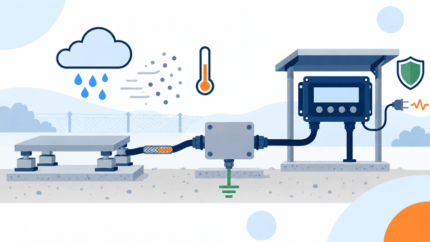
Environment and power quality are selection criteria, not accessories. Enclosure protection, mains voltage stability, ambient temperature, dust, and moisture all affect reading stability. So do cable shielding and grounding. Treat the indicator as one node in a chain: load cell → shielded cable → junction box → indicator.
Environment questions I ask buyers
- Indoor, semi-outdoor, or fully outdoor? Sun, rain, and condensation change the enclosure requirement.
- Dust or washdown? Food processing and cement plants pull in opposite directions — one needs washdown resistance, the other needs sealing against fine powder.
- Mains stability? In several of the markets we serve, supply voltage fluctuates significantly and generators are common. Ask about voltage range and whether the customer runs unstable power. This detail changes the recommendation.
- Temperature range? Cold storage and desert out