

Choosing the right load cell capacity is the single decision that determines whether your weighing system delivers reliable accuracy or becomes an expensive problem. Too many buyers match the load cell's rated capacity directly to their maximum weighing range—then face overload damage, poor resolution, or both. The good news: a structured calculation method eliminates most of these risks before you place a purchase order.
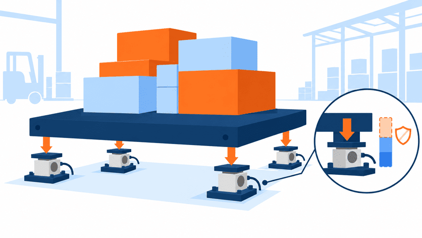
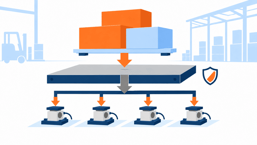
The correct load cell capacity is never equal to your maximum weighing range. It must account for dead load (the weight of your platform, hopper, or fixture), a safety factor appropriate to your application type, dynamic impact forces if applicable, and the number of load cells sharing the total load. The general formula is: single-cell rated capacity ≥ (max live load + dead load) × safety factor ÷ number of cells. Following this method prevents the two costliest mistakes—under-sizing that causes overload failure and over-sizing that kills measurement resolution.
I've spent over a decade helping scale manufacturers, distributors, and system integrators specify the right load cell capacity. In that time, I've watched the same mistakes repeat across markets—from the Middle East to Southeast Asia, from simple bench scales to automated packaging lines. Below, I'll walk you through the exact process we use when advising our customers, including worked examples, the variables most people miss, and the real-world failures that taught us these lessons the hard way.
Why Is Equating Max Weighing Capacity with Load Cell Rated Capacity a Mistake?
This is the most common error we encounter. A buyer needs a platform scale rated for 500 kg, so they order a 500 kg load cell. It sounds logical—but it ignores every other force acting on the sensor.
The load cell's rated capacity must cover all forces applied to it, not just the net weight of the goods being measured.[1] This includes the dead load of the weighing platform, the safety margin for unexpected overloads, and the way multiple cells divide the total force. Skipping any of these variables leads to either chronic overload or wasted sensitivity.
The Complete Capacity Formula
Here is the formula we walk every customer through:
Single-cell rated capacity ≥ (Max Live Load + Dead Load) × Safety Factor ÷ Number of Load Cells
Let me break down each variable:
| Variable | Definition | Typical Range |
|---|---|---|
| Max Live Load | The heaviest net weight you will ever place on the scale | Defined by your scale's rated capacity |
| Dead Load | Weight of the platform, frame, hopper body, or fixture sitting on the load cells permanently | Often 20–50% of the live load for steel platforms[2] |
| Safety Factor | Multiplier to protect against occasional overloads, uneven loading, and environmental stress | 1.25–2.0 depending on application |
| Number of Load Cells | How many sensors share the total load | 1 for bench scales, 3–4 for platform/floor scales, 6–8+ for truck scales |
A Worked Example
Let's say you are building a floor scale with:
- Max live load: 3,000 kg
- Dead load (steel platform + frame): 600 kg
- Safety factor: 1.5 (moderate industrial use)
- Number of load cells: 4
Calculation:
Single-cell rated capacity ≥ (3,000 + 600) × 1.5 ÷ 4 = 1,350 kg
The nearest standard rated capacity above 1,350 kg is 1,500 kg (or 2,000 kg, depending on available models). So each of the four load cells should be rated at 1,500 kg or 2,000 kg—not 3,000 kg, and certainly not 750 kg.
If this buyer had ordered four 500 kg cells to match a rough quarter of the max live load, they would have overloaded the sensors the moment the empty platform was installed. We've seen this exact scenario with a customer building multi-cell platform scales—they initially specified cells based solely on the advertised weighing range divided by four, completely ignoring the 600+ kg dead load contribution. The result was zero-point drift within weeks and eventual cell replacement.
What Happens When You Skip the Dead Load?
- Zero-point shift: The load cell operates near its rated limit even with no goods on the scale, leaving almost no usable range for actual measurement.
- Accelerated creep: Sustained load near full capacity causes permanent deformation of the elastic element over months[3].
- Reduced overload margin: A minor accidental overload—a forklift bump, an extra pallet—pushes the cell past its safe overload rating and can cause immediate failure.
The takeaway: never skip the dead load estimate. If you don't know the exact weight of your platform or hopper, weigh it or ask your fabricator for the steel weight. An approximation is far better than ignoring it entirely.
Why Do Dynamic Applications Need a Separate Impact Factor?
Static specs on a load cell datasheet assume the load is applied gradually and held steady. In reality, many industrial weighing applications involve impact, vibration, or rapid load changes that generate momentary forces far exceeding the static weight.
In hopper filling, packaging machines, conveyor check-weighers, and batching systems, the instantaneous force during material drop, bag impact, or product transfer can be 1.5 to 3 times the static load[4]. If you size the load cell for static weight alone, you are chronically overloading it during every operating cycle.

The Modified Formula for Dynamic Applications
For any application with moving loads, material impact, or vibration, add a dynamic coefficient (Kd) to the formula:
Single-cell rated capacity ≥ (Max Live Load × Kd + Dead Load) × Safety Factor ÷ Number of Load Cells
| Application Type | Typical Dynamic Coefficient (Kd) |
|---|---|
| Static platform scale, floor scale | 1.0 (no impact) |
| Hopper filling with gentle gravity feed | 1.2–1.5 |
| Packaging line with bag drop | 1.5–2.0 |
| Conveyor check-weigher with product transfer | 1.5–2.5 |
| Heavy material dumping (aggregate, scrap) | 2.0–3.0 |
A Real Case: Packaging Line Early Failure
We encountered a customer who was building a packaging line that fills and seals bags of a granular product. Each filled bag weighed approximately 25 kg. They selected their load cells based on the 25 kg net weight of the bag plus a modest safety factor—a seemingly reasonable approach for someone unfamiliar with dynamic loading.
What they didn't account for was the impact force when each filled bag dropped onto the check-weighing station. Even a short drop of 50–100 mm generates a momentary peak force well beyond the static 25 kg. Within a few months of production, the load cells showed degraded repeatability and premature zero-point drift. The sensors hadn't been "defective"—they had been systematically overloaded hundreds of times per shift.
After reviewing the application with the customer, we recommended load cells with a higher rated capacity that accounted for a dynamic coefficient of approximately 2.0. The replacement cells have been running without issue.
How to Estimate Your Dynamic Coefficient
If you're unsure what dynamic factor to apply:
- Identify the load application method. Is material dropped, poured, placed by hand, or conveyed?
- Estimate the drop height and speed. Even a few centimeters of free fall matters.
- Consider the cycle frequency. High-speed packaging lines accumulate fatigue stress faster than slow batch processes.
- Consult your load cell supplier. At ANTORIS, we routinely help customers estimate the dynamic coefficient based on their process description, because this number is rarely published in any standard reference table—it depends on the specific mechanical setup.
The key principle: when in doubt, increase the dynamic coefficient rather than reduce it. The cost of selecting a slightly higher capacity cell is trivial compared to replacing failed sensors and halting a production line.
How Does Over-Sizing Kill Your Measurement Accuracy?
Most articles about load cell capacity selection only warn you about under-sizing. But in our experience advising scale manufacturers, over-sizing is equally damaging—it just fails silently instead of catastrophically.
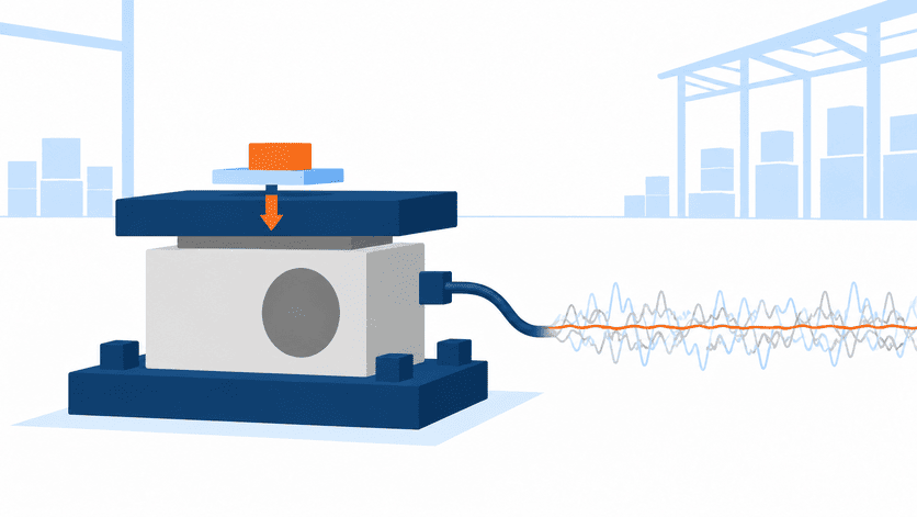
When you install a load cell with far more capacity than your application needs, you force the weighing system to operate in the bottom fraction of the cell's output range. The result is degraded resolution, poor signal-to-noise ratio, and accuracy that falls well short of what the load cell's datasheet promised.
Why the Ideal Working Range Is 30–70% of Rated Capacity
A load cell's rated output—typically 2 mV/V for many industrial models[5]—is the full-scale electrical signal at rated capacity. When your actual working load only uses 20–30% of that rated capacity, the electrical signal representing your entire weighing range is a small fraction of the cell's full output.
Here's a concrete comparison:
| Scenario | Load Cell Capacity | Working Range | Signal at Max Working Load (at 2 mV/V) | Effective Resolution |
|---|---|---|---|---|
| Properly sized | 200 kg | 0–150 kg (75% of capacity) | ~1.5 mV/V | High |
| Over-sized | 500 kg | 0–150 kg (30% of capacity) | ~0.6 mV/V | Reduced |
| Severely over-sized | 1,000 kg | 0–150 kg (15% of capacity) | ~0.3 mV/V | Poor |
At 0.3 mV/V, your weighing indicator is trying to resolve meaningful weight differences from a tiny electrical signal. Electrical noise, temperature drift, and cable interference[6]—which would be negligible at full-scale output—now represent a significant percentage of your working signal. The result:
- Unstable readings that fluctuate by one or more display divisions
- Poor repeatability, especially at low loads
- Inability to achieve the verification divisions your scale design requires
The "Safety" Trap
I've seen this pattern repeatedly: a buyer selects a 500 kg load cell for a 150 kg application because "bigger is safer." The load cell will never be overloaded—that's true. But the scale it's installed in cannot achieve the 50 g divisions the customer expected. They blame the indicator, the wiring, or the environment, when the root cause is the mismatch between load cell capacity and working range.
The optimal approach is to size the load cell so your normal working range falls between 30% and 70% of rated capacity.[7] This keeps the output signal strong enough for high resolution while leaving headroom above 70% for occasional peak loads, dead load contribution, and safety margin. The formula from the first section is specifically designed to land you in this sweet spot—if you apply it correctly, you naturally avoid both under-sizing and over-sizing.
How Do Different Load Cell Structures Affect Capacity Selection?
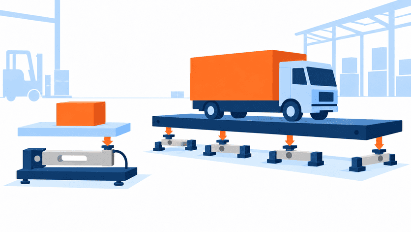
Not all load cells share load the same way. The structure and mounting configuration of the load cell directly influences how you calculate the required capacity per cell. A single-point cell on a bench scale and a shear-beam cell on a multi-cell truck scale follow different selection logic.
Understanding which structure applies to your application—and how load distribution works for each—prevents the kind of mismatch that leads to premature failure or poor corner accuracy.
Structure-by-Structure Guide
| Load Cell Structure | Typical Application | Number of Cells | Key Capacity Variable |
|---|---|---|---|
| Single-point | Bench scales, platform scales (small), counting scales | 1 | Cell carries the entire load + platform weight; off-center loading is compensated internally |
| Shear beam | Medium platform scales, conveyor scales, hopper scales | 2–4 | Each cell carries a fraction of total load; uneven load distribution must be considered |
| Double shear beam | Truck scales, large platform scales, tank weighing | 4–8+ | Load sharing depends on foundation levelness and load positioning; worst-case corner loading matters |
| S-type (tension/compression) | Hanging scales, hopper suspension, batching systems | 1–4 | Tension applications must account for container weight as dead load; dynamic forces during filling |
| Column / canister | Truck scales, silo weighing, heavy industrial scales | 3–8+ | Very high capacities; foundation settlement and thermal expansion affect load sharing |
| Compression (button/disk) | Compact industrial scales, force measurement | 1 | Alignment and load introduction method critical; rated capacity must cover peak compression forces |
Single-Point Cells: The Simplest Case
For a single-point load cell in a bench or small platform scale, the capacity formula is straightforward—one cell carries everything. The main variables are the platform weight (dead load), the maximum net load, and the safety factor. Single-point cells also provide inherent off-center compensation within their rated platform size[8], so load distribution is not a concern as long as the platform dimensions stay within the cell's specification.
Multi-Cell Configurations: Why Even Division Is a Myth
In a four-cell floor scale or truck scale, it's tempting to assume each cell carries exactly one-quarter of the total load. In practice, load distribution is never perfectly even[9]. Factors that cause uneven loading include:
- Off-center load placement (a pallet placed closer to one corner)
- Structural flex of the platform
- Foundation unevenness (especially for truck scales installed on concrete pads)
- Thermal expansion differences between mounting points
This is one reason the safety factor exists—but in applications with severe off-center loading, the safety factor alone may not be sufficient. Some engineers use a load distribution factor of 1.1–1.3 applied to the theoretical per-cell load[10] to account for the worst-case corner.
Matching Structure to Application
When selecting load cell capacity, always start by confirming:
- Which structure type suits your mechanical design and mounting constraints
- How many cells will share the load
- What the realistic worst-case load distribution looks like—not the theoretical even split
At ANTORIS, we manufacture single-point, cantilever beam, shear beam, double shear beam, S-type, column, compression, and miniature load cells. When a customer sends us their scale design and intended application, capacity recommendation is always our first step—before discussing output specifications, material, or cable length. Getting the capacity right is foundational; everything else follows.
Frequently Asked Questions
What safety factor should I use for load cell capacity selection?
There is no universal safety factor. For static applications like platform scales and bench scales, 1.25–1.5 is common. For dynamic applications with impact or vibration, 1.5–2.0 or higher is typical.[11] Harsh environments, heavy off-center loading, or regulatory requirements may push the factor higher. Always confirm with your load cell manufacturer for your specific application conditions.
Can I use a higher-capacity load cell "just to be safe"?
You can, but you sacrifice measurement accuracy. A load cell operating at only 15–20% of its rated capacity produces a very small output signal, leading to poor resolution, unstable readings, and difficulty meeting verification scale requirements. The ideal working range is 30–70% of rated capacity. Over-sizing for safety should be moderate and calculated—not arbitrary.
How do I estimate dead load if I don't have exact platform weight data?
Ask your steel fabricator or weigh the platform structure on an existing scale before final assembly. If neither option is available, estimate based on material and dimensions—for example, a mild steel plate of known thickness and area has a calculable weight. Even a rough estimate is far better than ignoring dead load entirely, which is the most common source of under-sizing errors.
Does altitude or temperature affect load cell capacity selection?
Altitude does not directly affect capacity selection. However, temperature extremes influence zero-point stability, creep behavior, and long-term fatigue[12]. In high-temperature or outdoor applications, selecting a load cell with a slightly higher safety factor—and verifying the cell's compensated temperature range on the datasheet—is a prudent practice.
When should I consult the manufacturer instead of calculating capacity myself?
Consult your manufacturer when your application involves dynamic forces you cannot easily quantify, unusual mounting configurations, extreme environmental conditions, or regulatory certification requirements. A good manufacturer will ask about
References
- How to Choose the Right Load Cell Capacity for Your ...
- What You Need to Know About Platform Loading
- What Is Load Cell Creep?
- INTEGRATED APPROACH TO DYNAMIC IMPACT LOADING
- What is Load Cell Sensitivity (mV/V) and Why is it Important?
- Design and Shape Optimization of Strain Gauge Load Cell for ...
- Load Cell Specifications Guide
- Why Use a Single Load Cell for Platform Weighing?
- Truck scales: Robust weighing solutions for industry
- How to Choose the Right Load Cell Capacity for Your ...
- Factor of safety
- Understanding Load Cell Temperature Compensation